Cost-effective Production Testing of Hollow-core Optical Fibers

Executive Summary
The development of hollow-core optical fibers (HCF) represents a paradigm shift in optical fiber communications. With demonstrated optical loss nearly 40% lower than pure silica core fibers and latency reductions of 30–47%, HCF technology promises to be transformative for data center interconnection, artificial intelligence infrastructure, and any application requiring real-time communication.
With such potential, HCF developers are understandably motivated to ramp up production as rapidly as possible. However, the structural differences between HCF and conventional single-mode fiber (SMF) are far from trivial. The combination of extremely low backscatter coefficients, a near-vacuum refractive index, and proprietary microstructure designs presents real and substantial challenges to production testing—challenges that must be overcome if HCFs are to be produced at volume and at a reasonable cost.
Photon Kinetics is well-positioned to address these challenges by adapting its proven “short-length” and “full-length” test station platforms—platforms that have served standard SMF manufacturers for over a decade—to enable cost-effective, high-volume HCF production testing.
Introduction
With demonstrated optical loss as low as 0.091 dB/km and a group index of approximately 1.003 versus approximately 1.468 for solid-core fibers, hollow-core fiber enables both faster and longer-reach links. But the very properties that make HCF so compelling also create unique challenges for production testing.
Production-level fiber characterization demands greater precision and needs to be more comprehensive than field testing: it must not only guarantee that each fiber meets its published specifications, but also provide the critical process control feedback that enables manufacturers to optimize yield and output. Moreover, this comprehensive testing must be performed quickly and reliably by production operators—not engineers—to keep the cost of measurement contained. These challenges must be solved if HCF is to be manufactured efficiently at high volume.
Key Challenges in HCF Production Testing
Transitioning hollow-core fiber from research and development to high volume manufacturing requires overcoming several interconnected testing challenges.
Absence of Industry Standards
Rapid development of any production test solution depends on a clear definition of test requirements: i.e., what properties are being measured, and to what level of precision? For conventional single-mode and multimode fibers, decades of work by standards bodies—ITU-T, IEC, TIA, and others—have produced a comprehensive library of generic fiber specifications and test procedures that fiber and cable manufacturers and test solution providers, like Photon Kinetics, rely on.
No such library yet exists for hollow-core fibers. Each HCF manufacturer is working with proprietary designs and no doubt has different test objectives as they seek to optimize their own unique microstructures. This lack of standardization means that production test solution providers must design flexible test platforms capable of accommodating a variety of potential test methods, rather than building platforms that are designed for a specific test technique or measurement.
Fiber Preparation and Handling
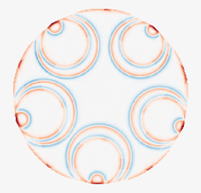
The complex internal structure of hollow-core fibers—potentially comprising over 32 unique air-to-glass interfaces—not only makes the creation of the high-quality end faces essential, but it also makes it more difficult than for solid-core fibers. The cleaving process must produce flat, defect-free fiber end faces without damaging any of the fiber’s numerous internal structures to enable reliable measurement of properties such as fiber geometry, but also fiber transmission properties that could be affected by damage to internal structures such as mode field diameter.
Additionally, it has been shown that air and gas infiltration or exfiltration at the ends of the fiber as it sits on the production floor after drawing can affect both transmission and OTDR measurements. Whether affected regions need to be removed prior to testing, and how to manage this phenomenon in a production workflow, are practical challenges that must be addressed.
Fiber Geometry
Complete geometric characterization of every air-to-glass interface—including the inner and outer cladding walls and the inner and outer walls of each of the nested tubes—is likely necessary for effective manufacturing process control. Given the sheer number of structures, this represents a dramatically more complex measurement task than the relatively straightforward geometry characterization of conventional fiber.
Compounding this complexity, it is likely that the fiber draw process can cause the co-mingling and distortion of interfaces between the fiber’s various components, which will require both improved edge detection algorithms and better fitting methods for useful characterization of these structures. It remains to be seen which of the many geometric properties of the HCF structure the industry will determine to be commercially specifiable, adding uncertainty to the development of measurement solutions.
Short-Length Transmission Measurements
“Short-length” transmission measurements—including cutoff wavelength, mode field diameter, and cut-back attenuation reference for standard SMFs—are typically performed on sample lengths of approximately two meters. For HCF, a fundamental question for these measurements remains unresolved: what sample lengths and what launch conditions should be used to best predict the fiber’s performance in the field?
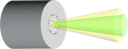
Sample lengths may need to be longer than the conventional two meters—perhaps 5, 10, or even 20 meters—to ensure that transient and lossy modes that can bias the short length measurements are eliminated. As far as launch conditions are concerned, the traditional overfilled launch (OFL) used for conventional fiber is generally not appropriate for HCF, as this type of launch would put light into the nested tube structures rather than confining it to the central air core.
More appropriate approaches would include a restricted beam optics launch—controlling both launch spot size and numerical aperture to target the central air core—or the use of a specially designed SMF or other type of launch fiber. Both can be automated in a production environment, but determining which approach best serves each manufacturer’s design will be an important early decision.
Full-Length Transmission Measurements
Full-length production measurements—OTDR, chromatic dispersion (CD), and polarization mode dispersion (PMD)—present their own set of challenges when applied to HCF.
OTDR
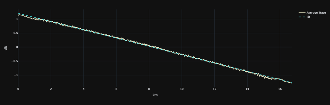
OTDR measurement of fiber attenuation, attenuation uniformity, location of point defects and fiber length is the measurement most significantly impacted by the unique properties of HCFs. Some of the OTDR testing issues unique to hollow-core fibers include the following:
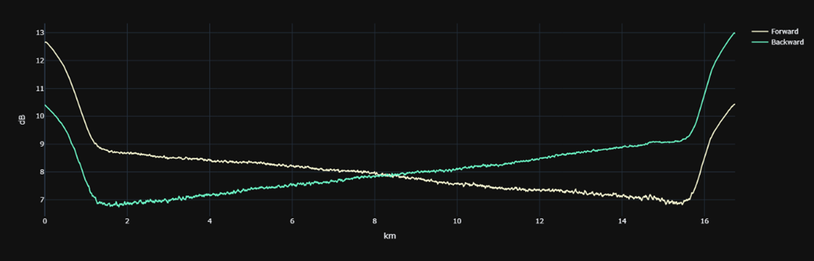
- The backscatter coefficient of hollow-core fiber is typically 14–20 dB lower than that of conventional SMF, resulting in substantially lower OTDR signal-to-noise ratio and noisier signatures. It is clear that higher-power conventional or amplified laser sources would improve OTDR signature quality and reduce averaging times, but these require significant design changes for most existing OTDR platforms.
- Potential variability of the backscatter coefficient in HCFs due to gas/air infiltration at the fiber ends necessitates bi-directional signature analysis. Fortunately, this has been standard practice for OTDR production testing for many years and does not represent a new requirement.
- High reflections at the coupling between the OTDR’s glass core SMF buffer fiber and the air core HCF under test, in conjunction with the large changes in backscatter coefficient, create significant attenuation dead zones which can affect both defect and end-to-end loss measurements. Reflection reduction through optical or electronic means, or both, will be necessary to maximize measurement accuracy and precision.
- The difference in group index between the OTDR buffer fiber and the HCF can cause location and length errors. In field testing, where locations relative to the front panel of the OTDR are important, this can be problematic. But in production this is largely irrelevant since signature analysis is typically confined to the fiber under test and buffer fiber lengths are ignored.
- Finally, as with any OTDR test application, HCF manufacturers will need to determine their own preferred balance of OTDR resolution, range, and averaging time—i.e., their ideal “OTDR performance envelope”—just as standard SMF manufacturers did in the past.
Chromatic Dispersion and PMD
In contrast to OTDR, the other principal full-length measurements—chromatic dispersion and polarization mode dispersion—are expected to be minimally impacted by the transition to HCF. In fact, existing CD and PMD test system signal-to-noise ratios should actually benefit from the lower attenuation of hollow-core fiber, potentially accelerating these measurements relative to conventional SMF due to higher SNR.
Photon Kinetics Solutions for HCF Production Testing
Photon Kinetics has been working closely with leading HCF developers to adapt its proven production test platforms to address the unique challenges described above. The result is a pair of complementary HCF test stations—one for short-length characterization and one for full-length measurements—that together provide the comprehensive production testing capability required to transition HCF from development into high-volume manufacturing.
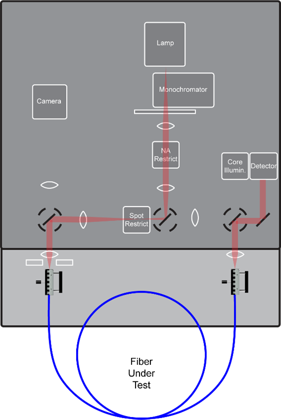
Short-Length HCF Station (2300A-H / 2300AG-H)
The short-length HCF station is built on the production-proven 2300 platform. In its “-H” configurations, the system provides seven spot and seven numerical launch restrictors— providing 49 possible launch combinations that allow HCF developers to systematically determine the optimal launch conditions for their particular fiber designs.
The combined spectral loss and geometry capability of the 2300AG-H variant is particularly useful to manufacturers, since it enables both transmission and geometry measurements with a single fiber preparation and loading process at the same test station, which enables significant improvement in test station throughput. This is an important advantage in an HCF production environment where fiber handling is potentially more time-consuming and technically demanding than for conventional fiber.
For manufacturers who prefer a fiber rather than beam optics launch, it is possible to integrate one or two automated 1050F Fiber Aligners with the 2300A-H or 2300AG-H to provide automated fiber-to-fiber coupling for either the launch and/or receive paths.
Full-Length HCF Station (FLS-H)
The FLS-H full-length station for HCF is a new configuration of the production-proven FLS (standard SMF) and FLS-M (multicore) test station platforms, being developed in active collaboration with leading HCF manufacturers. While the core component of all FLS configurations—the 8000 Production and Laboratory OTDR—is currently capable of characterizing HCFs, it is apparent that additional dynamic range and reduced dead zone performance would be beneficial for HCF measurement to not only increase the maximum measurable fiber length but also to reduce measurement time to production-acceptable levels.
Fortunately, the 8000 OTDR platform was designed specifically to facilitate these types of performance improvements. Its multi-configuration architecture, which already supports multiple detectors and up to 7 lasers, will readily accommodate the new opto-electronic components that will be necessary to both increase dynamic range and maintain acceptable attenuation dead zones for HCF applications.
OTDR signature analysis software updated to accommodate the unique features of HCF signatures will build on the 8000’s existing production-focused analysis capabilities, which already include fiber attenuation, length, attenuation uniformity, point defect location and characterization on bi-directional signatures. The FLS-H’s 1050F Fiber Aligners, with automated coupling loss optimization, will provide the low-loss, low-reflectance coupling between the SMF (or any other type of launch fiber) and the HCF under test.
At this point, significant changes to the 2880 chromatic dispersion and 2920 PMD measurement systems are not anticipated for HCF applications. As with the standard and multicore fiber FLS configurations, these instruments will be optically switched into the test path as required by the FLS software, as they are today for conventional fiber testing.
Conclusion
Realizing the full promise of hollow-core fiber technology requires the adaptation of proven production test solutions so that product quality can be maintained and costs controlled during the critical ramp-up from development to volume production.
Photon Kinetics has been working closely with HCF industry leaders to do exactly that—evolving its production-proven short-length and full-length test stations so they deliver the same capabilities and benefits to HCF manufacturers they have provided to SMF manufacturers for decades.
Importantly, these test stations are not simply individual, HCF-capable test instruments. They are comprehensive measurement solutions that address each of the unique challenges associated with hollow-core fiber testing: precision fiber cleaving and handling, launch conditioning, automated coupling of the HCF to the appropriate fiber or beam launch optics, and finally, HCF-focused data acquisition and analysis. Together, the automated 2300-H short-length and FLS-H full-length HCF stations will reduce the time and skill necessary to perform all critical HCF characterizations in production, playing an important role in enabling the transition from development to high-volume manufacturing.
Learn More
If you would like more information about our current HCF measurement solutions, or if you have unique HCF measurement requirements that you need help solving, please contact us at [email protected].